Skip to content

Matt Adam

Tech Blog

Menu
  • Home
  • Home Lab
    • Home Lab – Gen 1
    • Home Lab – Gen 2
    • Home Lab – Gen 3
  • VMware
    • VMware Cloud Foundation (VCF)
    • Avi Networks
  • Kubernetes
    • Openshift
    • K3s
    • Tanzu
      • Tanzu – TKGs (WCP)
      • Tanzu – TKG (TKGm)
    • Avi Kubernetes Operator (AKO)
  • About
  • Privacy Policy
Menu

Home Lab – Build the SuperMicro Server

Posted on July 12, 2022October 8, 2025 by Matt Adam

I wanted to post some pictures and give some insight into building the supermicro. This will not be a step by step guide as most of the other guides I have posted. There is a better guide on this blog. So use that blog in combination with the high res motherboard pictures below.

I think most of the confusion with building a server comes down to what components to buy, and where to connect the cables to the motherboard. I’ve documented all the components needed here. So all that is left is some pictures of the motherboard showing cable placement, etc.

Build Pictures

After unboxing the SuperMicro Mini-Tower Chassis, remove the outer cover and finally remove the 5 screws holding the motherboard tray.
Here’s the tray. The motherboard will mount onto this tray using the screws provided inside the mini-tower. Word to the wise: If the screw doesn’t screw in easily, it’s the wrong screw!
Before you install the motherboard, make sure you put in the back plate. You can see the tabs I’ve pre-removed. You can always take the tabs out later. The back plate snaps into place.
Top down of the board after being screwed into place. As you can see, I forgot the backplate and had to remove it all and do it again 🙂
Circled in Yellow is the Sata DOM
Red cables at the top circled in yellow are the SATA cables and go to your SSD/HD. Blue circle is for the power.
Blue circle is for the tower Fans. Yellow circle, is a better picture of the SATA cables. I went ahead and added and routed 2 cables (Even though i’m only using 1 ssd currently). That way if I want to add a new SSD later, it’s an easier process and I don’t have to pull out the motherboard to get the cables set.
Blue circle is for the additional tower fan that I purchased and installed.
Yellow circle is for the power button and USB ports in the front. Blue circle is an image of the fan that I installed. The fan blows air FROM the outside TO the motherboard.
Everything is done and screws put back. You can see the ethernet cables are ready to go, power is in. And VGA cable for a monitor.

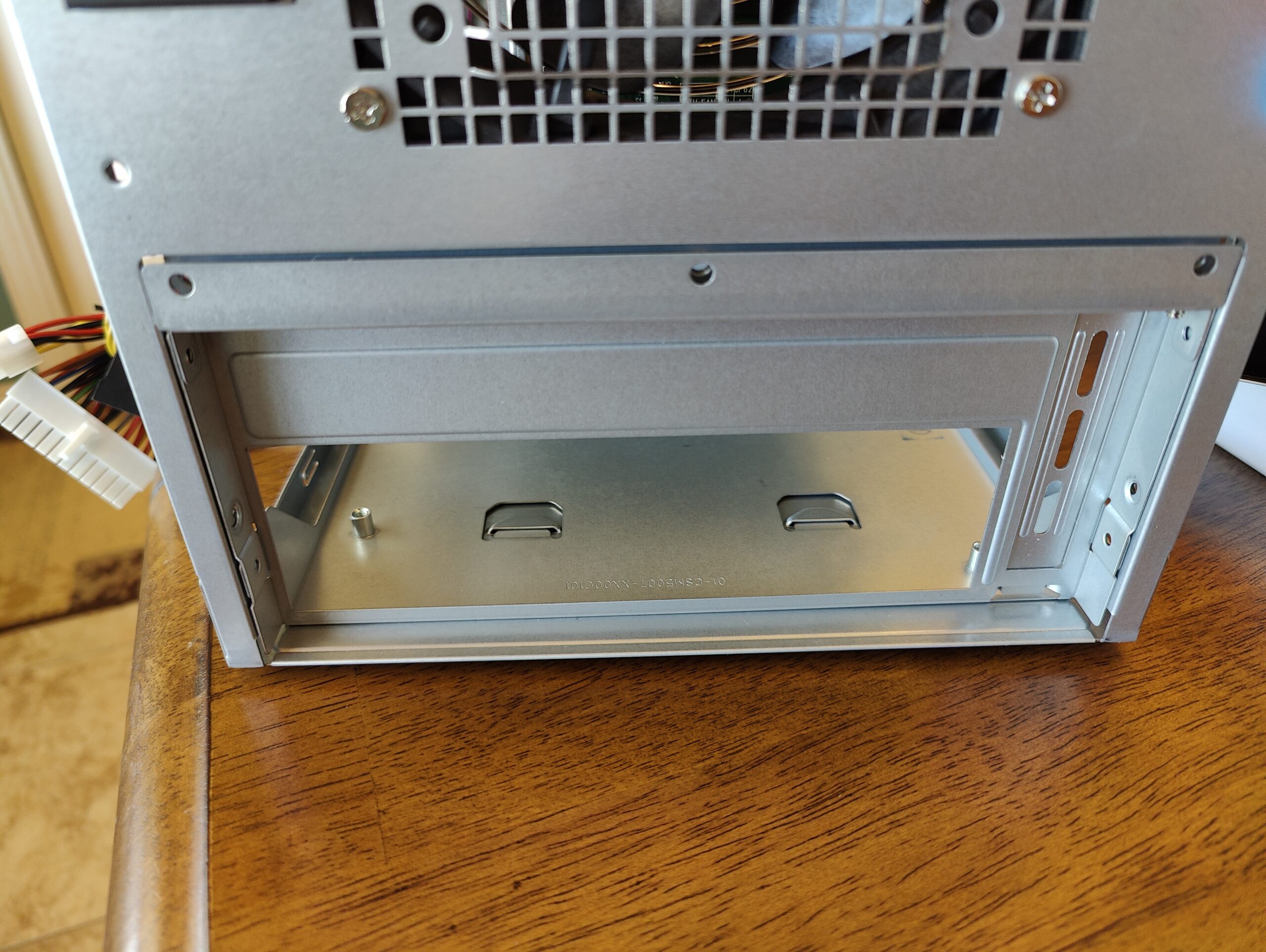
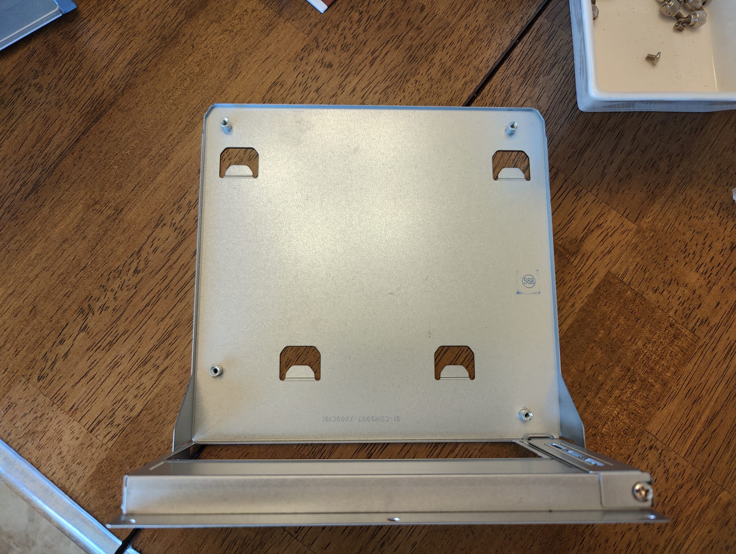
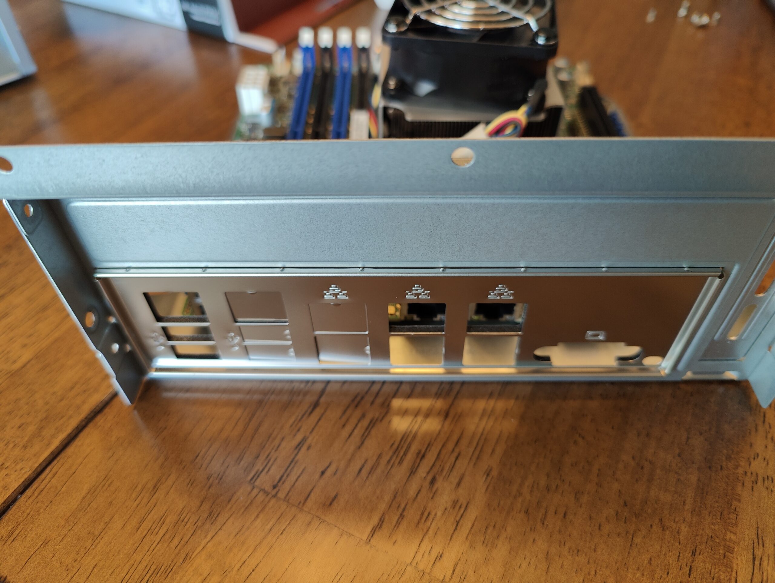
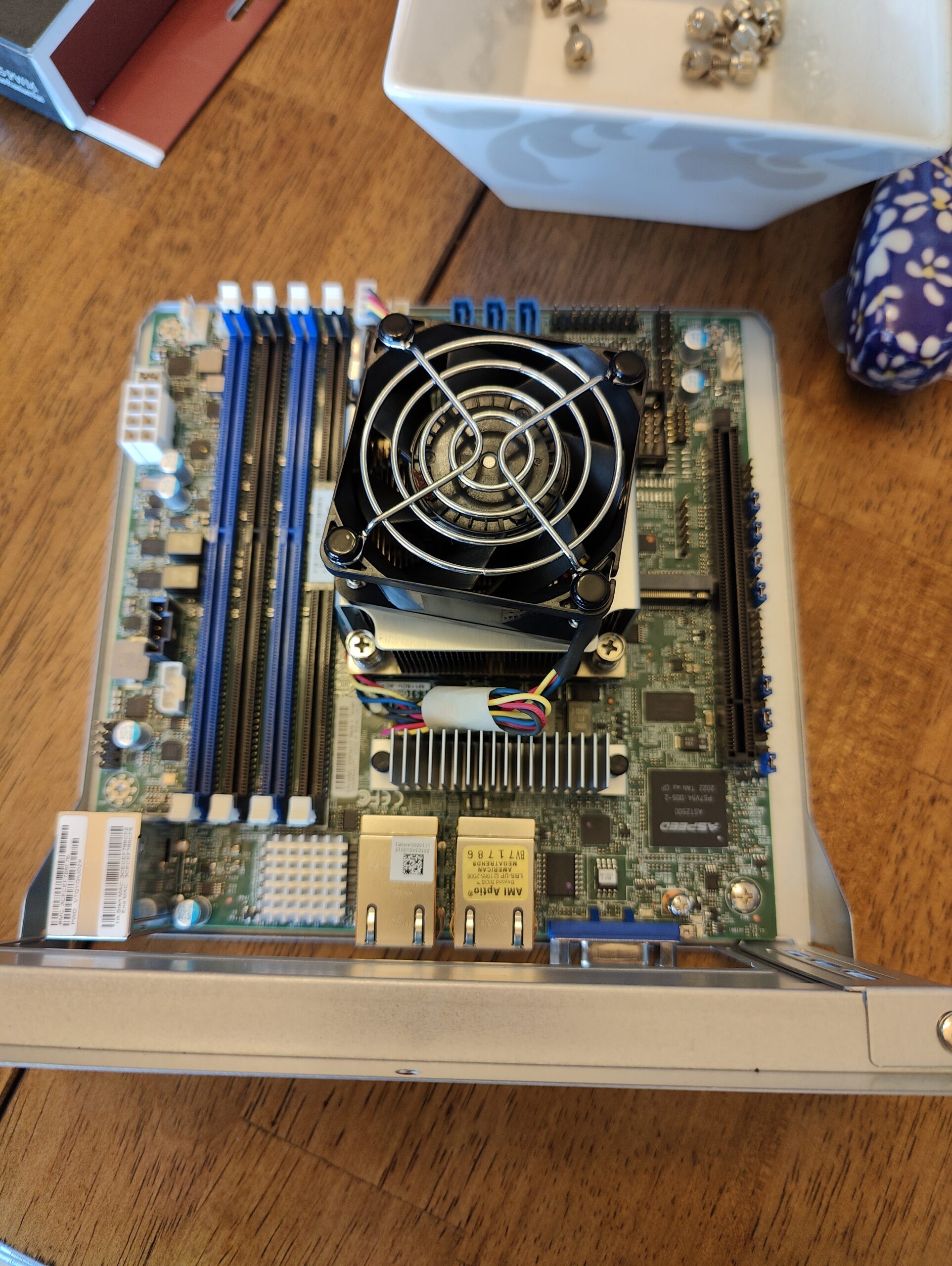
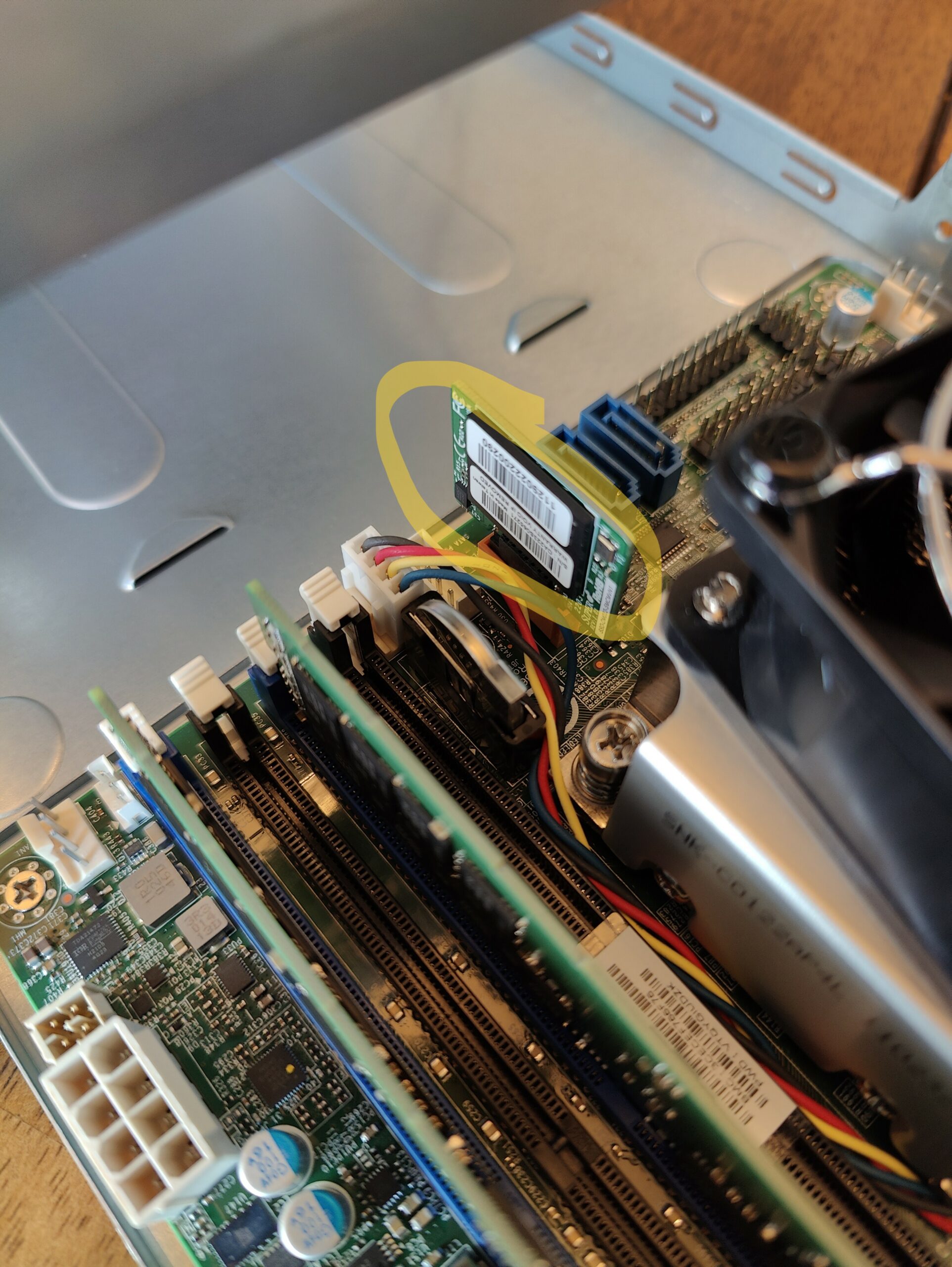
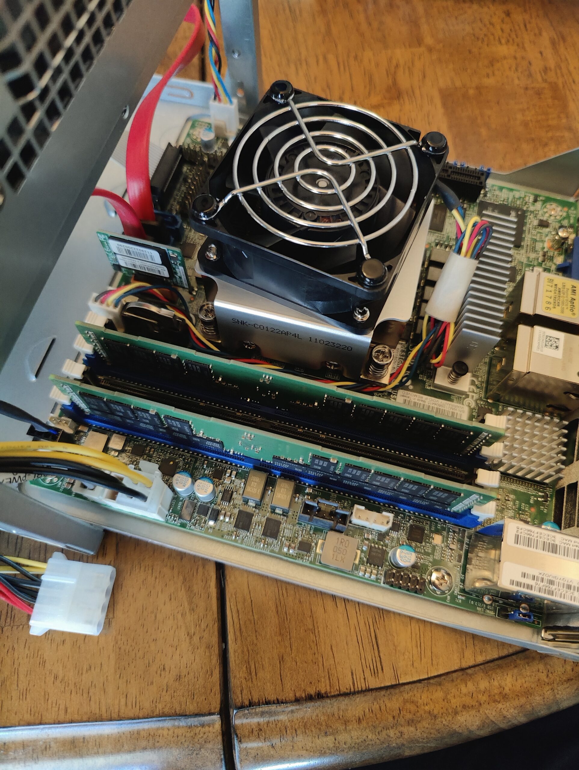
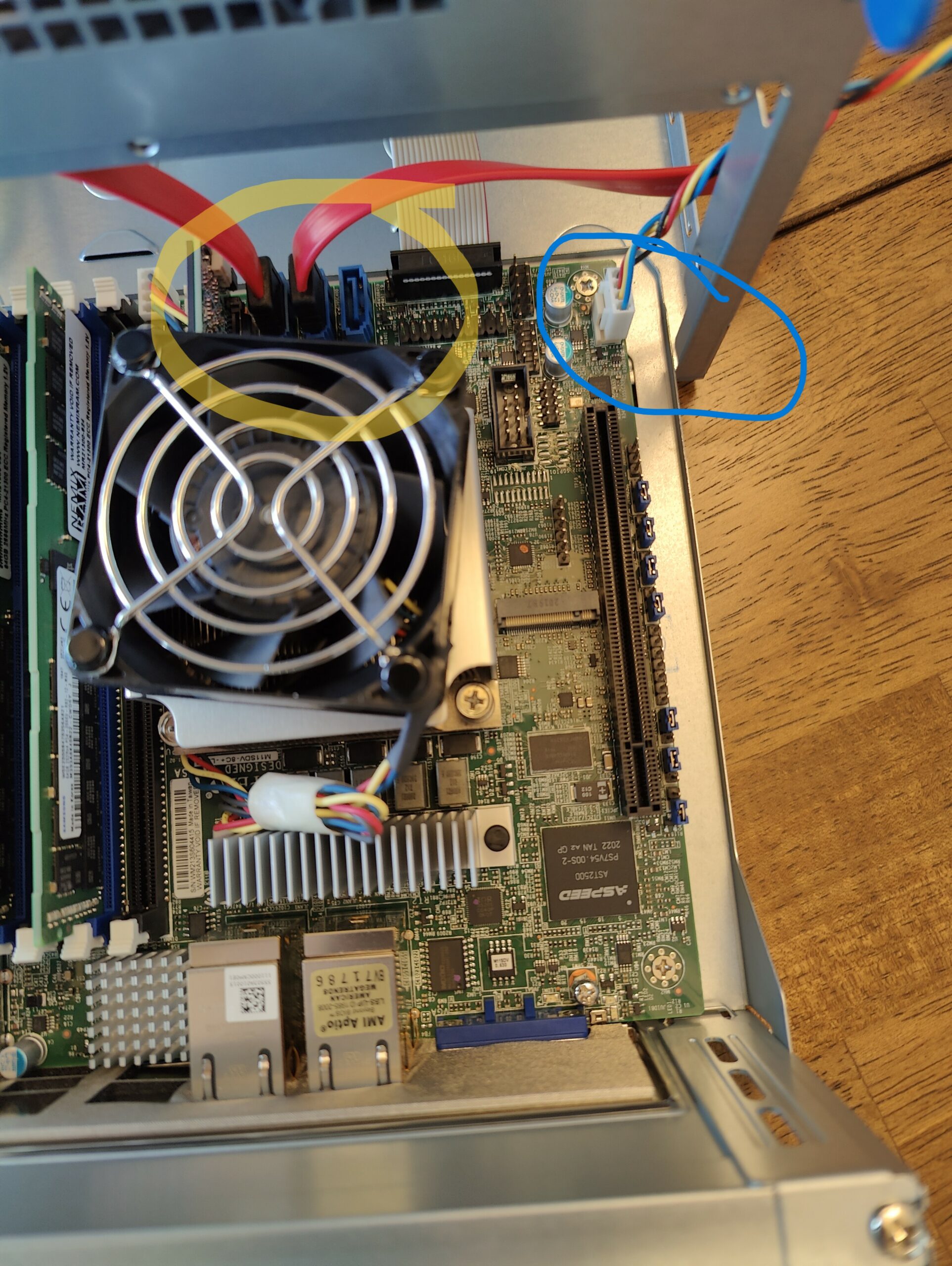
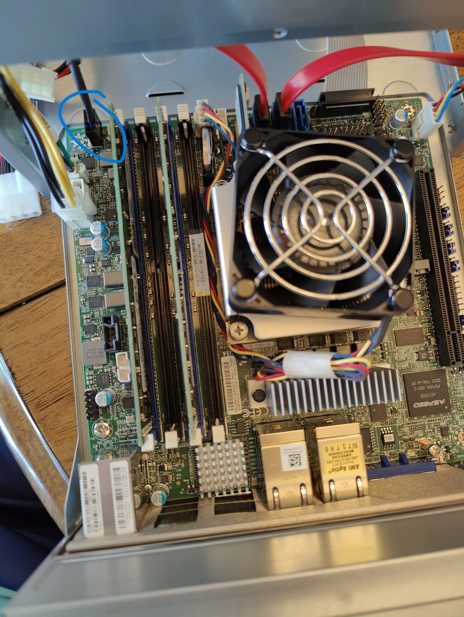
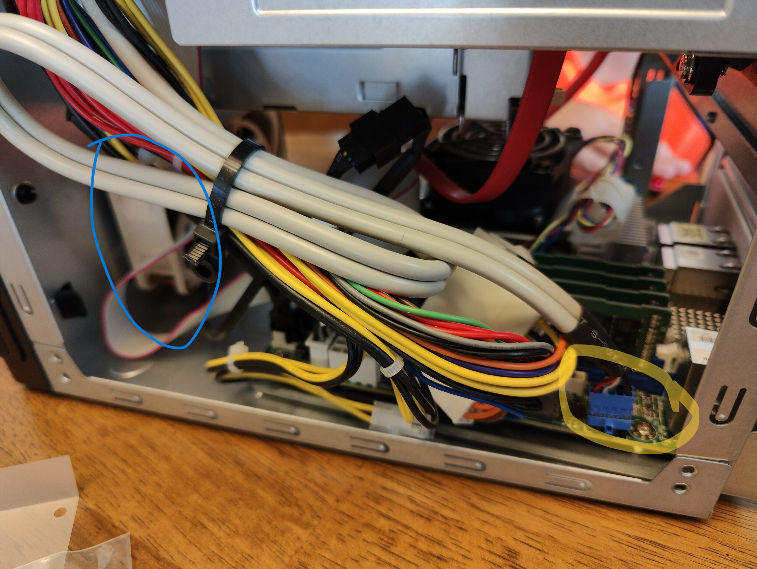
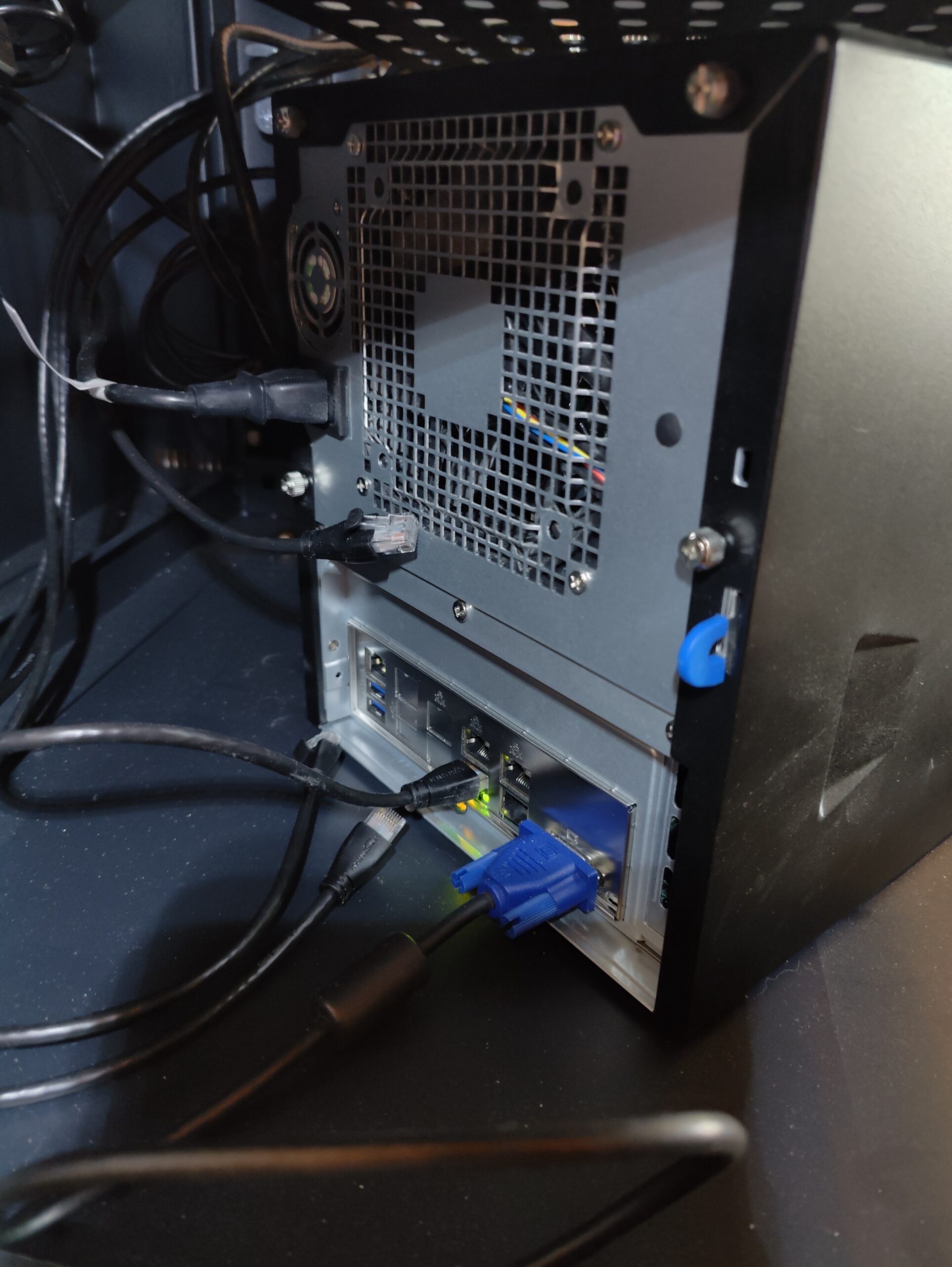
And that is basically everything. Hopefully the picture above can provide some good detail. Give me a comment if you need any additional help.

Social Media

  • LinkedIn
  • X
  • Bluesky
  • Mastodon

Recent Posts

  • Financial Solutions for ETF share classes
  • Power Consumption Tips for Efficient Home Labs: Save Energy, Save Money
  • Automating Deployments with Terraform in a Home Lab: A Simple Guide for Tech Tinkerers
  • Backup Strategies for Home Lab Data: A Beginner’s Guide to Keeping Your Files Safe
  • Home Lab Monitoring with Grafana and Prometheus: How to Track Your Systems Like a Pro
© 2026 Matt Adam | Powered by Minimalist Blog WordPress Theme